SERIES 2000 RESISTANCE WELDING CONTROLS
 Control Technology That Eliminates Variables That Cause Inconsistent Weld Quality
In designing the microprocessor-based Series 2000 Controls, we started with state-of-the-art technology and added unique innovations to provide a level of weld quality and consistency previously unobtainable.
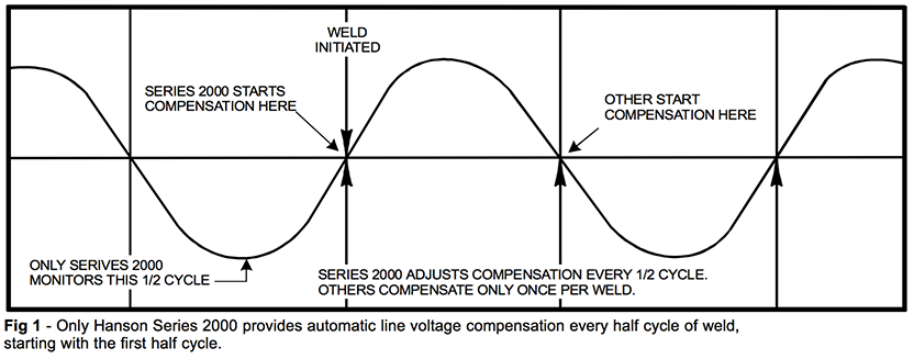
AUTOMATIC LINE VOLTAGE COMPENSATION
Precise voltage compensation is the answer to the familiar hot weld/cold weld problem, caused by variable line voltage which typically fluctuates +/- 10%. Our unique regulation circuit monitors input line voltage even when no welding is being done. Compensation for the first half cycle of weld is determined by the half cycle just before the weld is initiated. Unlike other controls, which compensate only once per weld, the Series 2000 adjusts compensation for each half cycle weld, based on the preceding half cycle voltage. The control circuit compensates for load variations caused by the welder as well as line fluctuations. This concept is defined in figure 1.
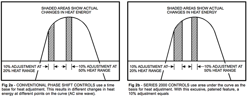
PHASE SHIFT HEAT CONTROL
The Hanson designed phase shift heat control is true area under the curve adjustment. It provides precise, consistent heat control at every point on the energy curve. The result being heat changes made between 20% and 80% phase angles are nearly linear. With conventional phase shift control, actual heat changes can vary significantly. For instance, a ten percent change measured at the 20% point of the curve would register much less of an energy change than it would at the 50% point. This is clearly defined and compared in figures 2a, and 2b.
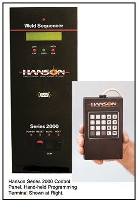
PROGRAMMABLE PRE-SELECTED WELD SCHEDULES
Weld schedules are programmed and recalled through the programming terminal. The control automatically controls percent heat, squeeze time, weld time and hold time.
FULL RANGE OF CONTROL FUNCTIONS
Manual and Automatic Mode Selector. Used to establish set-up parameters for each application. It allows single stepping of each sequence function when in the semi- automatic mode.
Heat/No Heat Selector Switch. Used for set up and dry cycling.
Polarity Selection Switch and Half-Cycle Control.
Back-to-Back SCR Firing Circuits.
BATTERY BACK-UP
All weld schedules, high and low limit settings and last current readings are retained in memory for approximately two months after the last power down.
INPUT/OUTPUT INTERFACE
A RS232 port permits interfacing with printers, SPC systems, or off lien management reporting systems. The standard unit works at 19200 baud rate which can be altered with a software change.
Up Slope/Down Slope
This feature is used in applications that require a gentle heat- up prior to achieving the full weld energy. It is also used in controlled cool-down applications to discourage joint embrittlement with some materials.
One application for this option is welding pre-plated materials. Up slope is used to get the plating to move and allow the electrode contact integrity with the base metal. This is particularly useful with galvanized or tin-plated materials. Up slope is often a good choice in upset type butt welding applicators to insure full contact integrity of the materials being welded prior to full energy turn on.
Pre Heat/Post Heat
This option is selectable in straight line steps unlike the slope functions. It is useful in brazing applications to preheat a joint and allow flux activation and therefore capillary flow (wets, or etches the joint). Post-heat is useful as an annealing function on air hardening or other delicate materials where joint brittleness is a concern.
WELD CONTROL OPTIONS
Weld Monitor
Weld monitors have been available for many years. Unfortunately, most of these devices are either current, or milli-volt second monitors, neither of which satisfy the basic requirement. To properly evaluate a weld, we must establish a correlation with what is happening electronically, and the mechanical test results. To do this we must have weld monitoring instrumentation capable of providing the necessary information. To properly monitor a weld, the equipment must measure current and area under the curve on each half cycle in A.C. applications, and measure current and area under the curve for each weld in D.C. applications. Further, it must be capable of calculating the product of these and reporting in half cycle increments, for A.C. applications. This product is called the weld energy, which is expressed in watt- seconds or joules.
 Finally, the weld monitor must be capable of accepting both upper and lower control limits with alarms to alert, or shut down the process.
Only Hanson Welding Machines, Inc. offers such a device. The optional weld monitor is an integral part of the Series 2000 Weld Control, and measures energy in real time, unlike remote add on monitors. It is fully programmable for upper and lower process control limits. The weld monitor audits every half cycle of weld, capturing the readings for current(in amperes) and milli-volt seconds (area under the curve). The product of these is expressed in joules of energy for each half cycle. The weld monitor protects against process shifts caused by dirty or worn electrodes, dirty or inconsistent product, equipment malfunctions, and countless other variables. The weld monitor stores the readings in memory for downloading to SPC packages for process capability analysis, or to printers for charting and evaluation.
ALL HANSON RESISTANCE WELDING EQUIPMENT IS NOW EQUIPPED WITH SERIES 2000 CONTROLS
Series 2000 Welding Controls are standard on Hanson's complete line of resistance welders, including the AP-2W Series of bench-top machines (1-20 KVA), floor mounted AB- 6 welders (30-200 KVA), hand-held welders and special purpose AUTOMATED welding machines.
